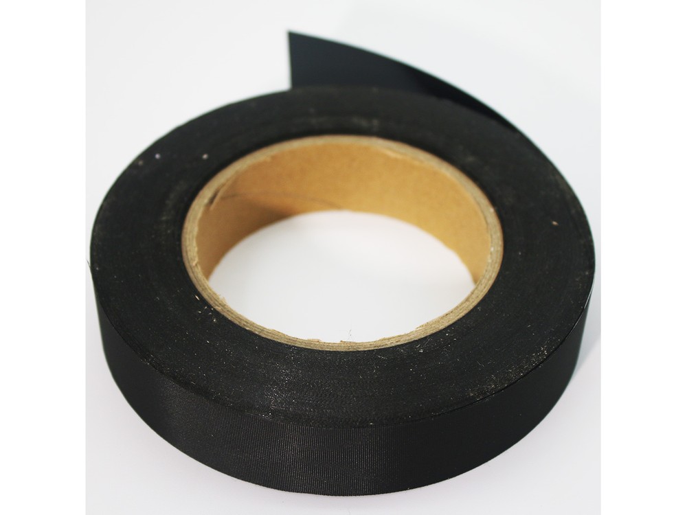
How Light Blocking Cloth Tape Is Made and Validated for Displays and Optical Modules
Black is not the same as verified light blocking. The control points, the optical measurements and the finished-module test that decide whether one exact tape model and lot can be released.
Black appearance is not the same as verified light blocking. A woven cloth can look uniformly black under room lighting and still transmit light through yarn gaps, return stray light from its surface, leak at a cut edge, lift from a low-energy substrate or squeeze adhesive into a narrow optical stack. A reliable decision links one exact tape construction to a defined measurement method and to the finished assembly.
This guide is for display, backlight, camera-module, sensor and die-cut engineering teams. It sets out the control points in making the tape, the optical measurements that mean something, and the final-module test that decides release. It is also explicit about what we have and have not published.
What we publish today, and what we do not
- Models. Eight light-blocking cloth tape models: L012-193, L112-193, L020-193, L120-193, L008-193, L108-193, Z1L020-193, Z1L120-193. The product page lists them with the construction as opaque, matte black, fine woven fabric, anti-fraying die-cut edge.
- Optical data. The product page says “opaque — model-level test data on request”. No transmission, optical-density or reflectance figure is published for any model, and none of the eight has a datasheet on the datasheets index. This page therefore contains no optical number, and nothing here should be read as a measured ONEI value.
- Quality system. The IATF 16949 certificate (CB02157) covers the quality management system of the Mingguang site within its stated scope. It says nothing about optical density, reflectance, peel or cleanliness of any tape.
1. Start with the optical failure mode
Locate the unwanted light path before choosing a tape. Through-material transmission passes through the backing or its pores. Surface reflection returns incident light into the optical path. Edge or gap leakage occurs around a die-cut window, an overlap, a corner or a housing interface. Mechanical leakage appears later when the tape shrinks, lifts, wrinkles or moves after temperature, humidity or assembly stress. These need different controls, so do not collapse them into one word such as “opacity”.
| Observed problem | Likely mechanism | Evidence to request |
|---|---|---|
| Bright points through the taped area | Pinhole, yarn gap or insufficient optical density | Spectral or photometric transmission record on the exact construction and thickness |
| Halo along a window or housing edge | Die-cut geometry, gap, edge lift or insufficient overlap | Dimension report, edge inspection and a powered-module light-leak image under agreed exposure |
| Ghost reflection near a sensor or lens | Surface reflectance or gloss too high for the optical path | Spectral reflectance or agreed gloss measurement with the instrument geometry stated |
| Leakage after ageing | Adhesive lift, shrinkage, curl, contamination or substrate mismatch | Ageing plan on the real substrate, then an optical and adhesion recheck |
| Particles or loose fibres | Cutting damage, fraying or handling contamination | Edge microscopy, a particle or cleanliness method and the converter process record |
2. Freeze the exact construction before testing
A valid report identifies the model, suffix and revision together with the backing fibre and weave, the blackening or coating route, the adhesive chemistry, total thickness and tolerance, release liner, roll dimensions, winding direction and converted-part drawing. A change in adhesive, backing, black layer, thickness or liner can change transmission, reflection, converting behaviour and assembly performance. Do not combine a thickness from one grade with an optical claim from another.
- Identify the exact roll and converted-part model, not only the family name “light-blocking cloth tape”.
- Record the approved master sample and the colour or surface-finish tolerance.
- Fix the substrate side, adhesive side, liner side and machine direction on the drawing.
- Define the deliverable: slit roll, kiss-cut part, frame, window mask or multilayer laminate.
- Control revisions so a report cannot be reused after an unreviewed construction change.
3. The manufacturing route, and what to ask to see at each step
Our manufacturing page describes the route from weaving through dyeing, coating and lamination to slitting and cutting. For an optical part, these are the records a buyer should expect to be able to ask for at each stage. They are the control points to request, not a statement that every item is measured on every lot today.
| Stage | Record to ask for | Risk it guards against |
|---|---|---|
| Incoming fabric | Lot, construction, width, thickness or mass, shade, visible defects | Wrong cloth, pores, streaks, contamination, unstable dimensions |
| Blackening and finishing | Recipe revision, process conditions, approved standard, optical sample result | Non-uniform transmission or reflection despite an acceptable colour |
| Adhesive preparation | Raw-material lots, batch ID, mixing record, solids or viscosity where controlled | Adhesion drift, gel, particles, coating defects |
| Coating and drying | Line, speed, coat weight or total-thickness map, oven zones, web position | Cross-web or machine-direction non-uniformity, residual solvent, curl |
| Slitting and winding | Blade, width, edge condition, tension, splice, roll identification | Fraying, telescoping, width error, edge lift, damaged liner |
| Die cutting and packing | Tool and drawing revision, dimension report, edge and particle check, liner release | Misaligned windows, burrs, fibres, adhesive ooze, part mix-up |
4. Measure transmission and reflection with stated conditions
An optical number means something only when the method and conditions are stated. ISO 5-2 defines geometrical conditions for transmittance-density measurement, and ISO 5-4 defines reflection-density geometry that can support an agreed reflection measurement on other materials. These standards define measurement conditions; they do not certify a pressure-sensitive tape or a finished display.
ASTM D1003 measures haze and luminous transmittance of essentially transparent plastics. It may be relevant to a transparent layer when a customer specifies it, but it is not automatic proof that an opaque black cloth tape has “zero leakage”. For an optical module, define the source spectrum or wavelength range, source intensity, aperture or illuminated area, detector and geometry, background, specimen conditioning, number of layers, detection limit and acceptance criterion. If the requirement is “no visible leak”, also define the observer, dark adaptation, distance, exposure and image processing: a photograph taken with free settings is not a reproducible test.
| Property | What to record | Boundary |
|---|---|---|
| Through-material transmission | Spectral transmittance or an agreed photometric transmission; density calculated only under the agreed method and valid range | A high result on a flat coupon does not prove edge sealing in a module |
| Surface reflection | Spectral reflectance, reflection density or an agreed gloss value, with geometry and backing stated | “Matte black” is a visual description until a limit and method are defined |
| Edge and gap leakage | A powered-assembly test with the production die-cut geometry, housing and source settings | Coupon opacity cannot reveal gaps, edge lift or insufficient overlap |
| Appearance consistency | Approved master, instrumental colour or reflectance data where agreed, controlled illumination | Colour agreement does not establish transmission or adhesion |
| Detection limit | Instrument range, check, background signal, reporting convention for below-limit results | Do not turn “below detection” into an absolute zero |
5. Validate adhesion on the real substrate
Optical success is lost if the tape lifts. ISO 29862 gives peel-adhesion methods, including 180-degree peel from stainless steel, and ISO 29863 measures static shear under constant load. They make results comparable; they do not replace testing on the actual display frame, polycarbonate, coated metal, foam, film, flexible circuit or lens barrel. Record cleaning, application pressure, dwell, temperature, humidity and peel speed, and recheck adhesion and optical leakage after the customer’s temperature, humidity, thermal-cycle, vibration or ageing sequence.
6. Qualify converting and die-cut edges
A roll that passes optical testing can fail after conversion. Tool clearance, support film, liner, machine direction and part orientation change fraying, dimensional stability and adhesive flow. Validate the smallest bridge, the narrowest border, the internal corner and the liner handling on the actual drawing, and inspect edge fibres, burrs, adhesive ooze, tolerance, missing parts, liner release and contamination. “Anti-fraying” should be a verified converted-part outcome, not a universal family claim.
7. Use a lot sampling map
One centre specimen cannot represent a coated web. Sample across the width and through the run; the number and positions follow the customer agreement and the process risk. Record roll ID, web position, equipment, method revision, conditioning, operator, result and disposition, and keep a retention sample from the released lot.
| Checkpoint | Minimum record | Escalate when |
|---|---|---|
| Start, middle and end of run | Model, batch, roll position, thickness, appearance or optical check | A trend, an isolated pinhole or streak, or a result near the limit |
| Across the web | Left, centre and right, or a risk-based map | A cross-web difference or edge-zone defect |
| Slit rolls | Parent jumbo link, slit number, width, edge and winding inspection | Fray, telescoping, contamination, width drift, damaged liner |
| Converted parts | Drawing revision, tool position, dimensions, edge and particle check | Tool wear, bridge break, adhesive ooze, missing part, poor release |
| Retention sample | Sealed identifier and storage condition linked to lot release | A complaint, audit or change investigation that needs trace-back |
8. Build the evidence pack in the right order
- Company level: current certificate, legal entity, site, scope, validity. This supports the management system only.
- Exact model: controlled specification, construction, optical method, transmission and reflectance result, adhesion data, dimensions, revision.
- Lot level: a certificate of analysis or release record linked to material batches, coating run, jumbo roll, slit roll and converted-part lot.
- Change level: an approved change notice for any change of backing, blackening, adhesive, thickness, liner, process, tool or manufacturing site.
- Final assembly: the customer’s test on the real optical path, die-cut geometry, substrates, ageing sequence and pass criterion.
9. Release only after the finished-module test
The decisive test is the customer’s finished module. For a backlight or display, evaluate powered light leakage at the specified luminance and viewing conditions. For a camera or sensor, evaluate flare, ghosting, stray light or signal impact using the production optical stack. For a housing mask, inspect edge sealing and reflectance at the specified angles. Record the exact tape model and lot, die-cut revision, application process and assembly condition so that a later change can be judged against the approved baseline.
What to send us
Send the optical path, the drawing and the failure symptom rather than asking for a generic “100 % opaque” tape. Include the substrate, the thickness available, the die-cut geometry, the light source or display settings, the wavelength range, the transmission, reflection or leakage limit and its test method, the ageing sequence, the cleanliness level, the roll or part format, the expected volume and the project deadline. We recommend a candidate construction, say which evidence already exists, and set out the validation that remains. Export quotation, sample logistics and price are handled through EJOY, our Hong Kong sourcing arm.